

Last updated on February 19th, 2026 at 07:27 am
Today high availability is expected and should be used whenever possible. Whether it’s a network switch or server, there should be high availability, especially with the network infrastructure. For switching, virtual switch technologies provide redundancy for the switch infrastructure and connected hosts (members).
In this post, I will review a basic MLAG configuration on Arista switches, but I will not go into detail about virtual switch options. Though, during the MLAG configuration, compare Cisco’s vPC and MLAG.
MLAG (Multichassis Link Aggregation) and vPC (Virtual Port Channel) (virtual switch technologies) were developed to provide high availability and get around spanning-tree constraints/issues when connecting a host (switch, server, or other devices) using dual ethernet interfaces. Without either of these, the second ethernet link will be disabled by spanning tree.
With either of these virtual switch technologies, both host’s ethernet links will not be disabled and will remain up/active. Again, I won’t go into greater detail as numerous articles about this technology are available on the Internet.
If you are new to Arista, MLAG, or transitioning from Cisco vPC, I highly recommend the book “Arista Warrior, Second Edition.”
My first experience with these technologies is with Cisco’s vPC. I configured vPC on a Nexus 7010 switch pair, then expanded to Nexus 9K and 5K switch pairs. At the time, I was aware of MLAG but had no experience with it until I started working with Arista switches. In researching more about MLAG, I’m surprised how many vendors use the technology, though it may have a different name per vendor. Here is a link showing which vendors use MLAG https://en.wikipedia.org/wiki/Multi-chassis_link_aggregation_group.
MLAG & vPC Command Comparison
If you have experience with Cisco’s vPC and need to use MLAG or vice versa, I created a command comparison of the two. Some have said MLAG is simpler than vPC, but now, looking at the command comparison, it may be simpler by a narrow margin. One difference that stands out is that MLAG (in Arista) does not have a priority command like vPC. If you have experience with both, I want to hear your feedback.

Topology Overview
Here we will configure an MLAG between an Arista switch pair, an access port host, and a trunk host. In this configuration, the host names, IP addresses, and VLANs are examples for this article. The Cisco switches in this example can be any host, for example, a server. If a server, then the server’s network interfaces should be in a teaming configuration.
The diagram is taken from GNS3, where this configuration is taken (as well as production environments).
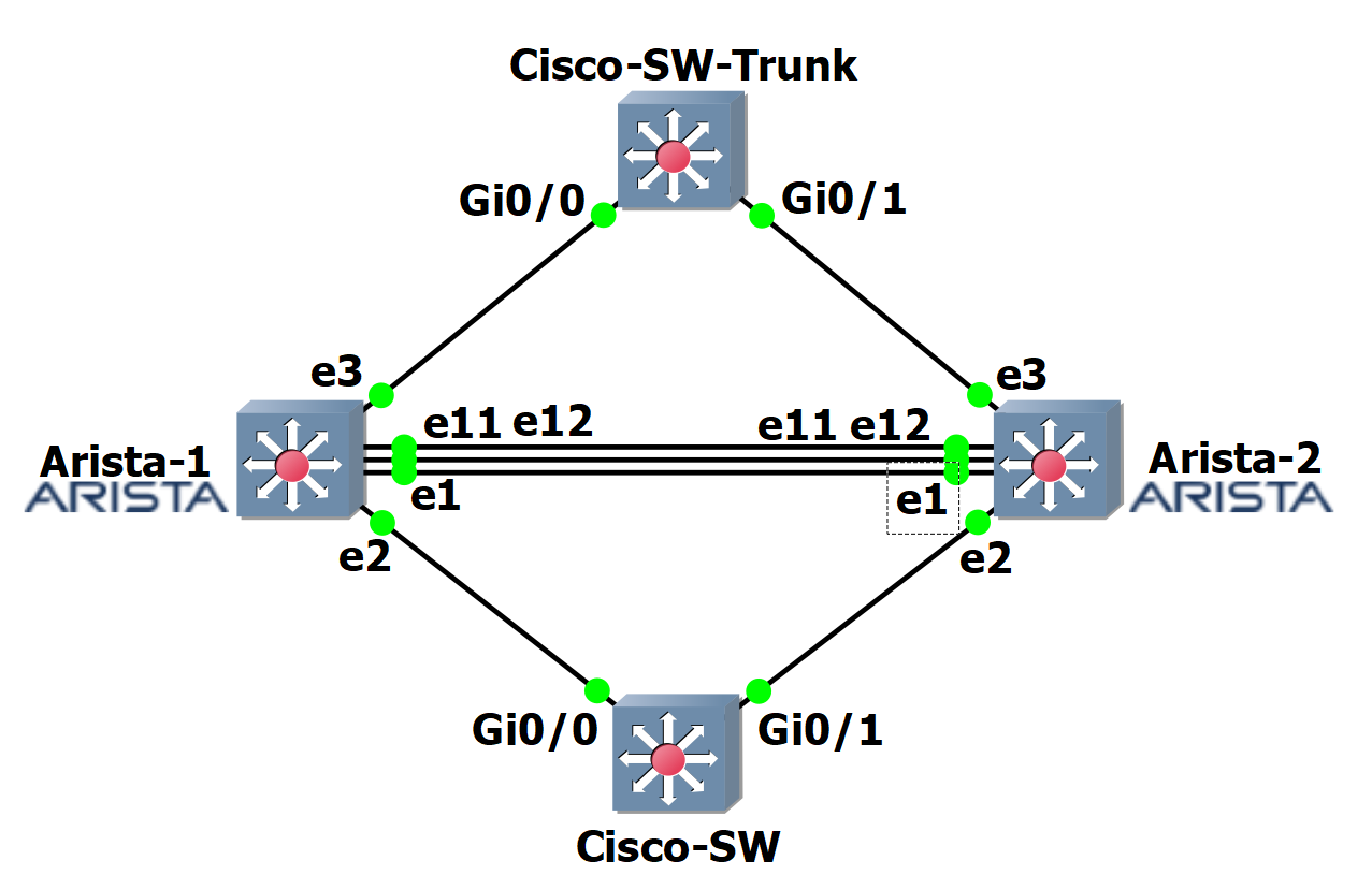
The following is an overview of the topology.
- Arista-1 and Arista-2 are MLAG peers, and the Peer Links are e11 and e12.
- The heartbeat link is e1 on each Arista switch. I recommend using a dedicated VRF for the heartbeat ports/link.
- Cisco-SW is the dual-connected Cisco switch connecting to Arista ports e2. This switch accesses VLAN 20.
- Cisco-SW-Trunk switch is a dual-connected Cisco switch connecting to Arista ports e3. This switch uses trunk ports allowing VLANs 10 and 11.
Configuration of MLAG (on Arista)
With switch virtualization, most commands are replicated on both switches. Some commands, like IP addresses, are unique to that switch.
Let’s GO!
On both Arista switches, configure VLANs, peer interfaces, and routing.
VLANs 10, 11, and 20 are used for the host Cisco switches.
config
vlan 10
exit
vlan 11
exit
vlan 20
exit
VLAN 4094 is used for the MLAG peers to communicate.
vlan 4094
trunk group mlagpeer
In this example, we will use ethernet ports 11 and 12 for the Peer Link in an EtherChannel.
interface eth11-eth12
channel-group 1000 mode active
exit
We configure the port channel from the last commands, specifying a trunk, and use the trunk group.
interface port-channel 1000
switchport mode trunk
switchport trunk group mlagpeer
exit
Because VLAN 4094 is used only for the Peer Link, we disable spanning tree for this one VLAN (only this VLAN).
no spanning-tree vlan-id 4094
IP routing is needed as the MLAG peers communicate via layer 3 and for any other IP routing.
ip routing
We will configure the interfaces and IP addresses for the Peer Link and Heartbeat on each switch.
Switch 1
hostname arista-1
Interface e1 is the Heartbeat interface as the IP address is referenced from the other peer, as you will see in the MLAG configuration. NOTE: with vPC or MLAG, the management interfaces or a dedicated interface can be used. Using a dedicated interface for the Heartbeat or Keep Alive is highly recommended. Also, a separate and dedicated VRF should be used.
There are multiple reasons not to use the management interfaces, for example, if the management interfaces are under attack (DoS), have an IP conflict, or are overwhelmed with management traffic. Any of these could cause the switch peers to think the other is unavailable, so an out-of-band, dedicated interface should be used.
If a dedicated (not management port) heartbeat link will be used (highly recommended), it’s recommended to place the interfaces in their own VRF. This command creates a VRF named heartbeat just for this purpose.
vrf instance heartbeat
interface e1
no switchport
vrf heartbeat
ip address 10.255.255.1/30
no shut
exit
Here is the interface used for MLAG and routing between the peers.
int vlan 4094
ip address 10.255.255.5/30
no autostate
exit
Switch 2
hostname arista-2
vrf instance heartbeat
interface e1
no switchport
vrf heartbeat
ip address 10.255.255.2/30
no shut
exit
int vlan 4094
ip address 10.255.255.6/30
no autostate
exit
This is where we bring it all together. The MLAG!
Switch 1 (arista-1)
mlag
local-interface vlan 4094
peer-address 10.255.255.6
peer-link port-channel 1000
peer-address heartbeat 10.255.255.2
dual-primary detection delay 10 action errdisable all-interfaces
domain-id arista-mlag
exit
Switch 2 (arista-2)
mlag
local-interface vlan 4094
peer-address 10.255.255.5
peer-link port-channel 1000
peer-address heartbeat 10.255.255.1
dual-primary detection delay 10 action errdisable all-interfaces
domain-id arista-mlag
exit
We added the “dual-primary detection delay 10 action errdisable all-interfaces” command to complete the Heartbeat configuration. Though the Heartbeat link is optional, it is highly recommended to prevent a split-brain situation.
Confirm the MLAG & Show Commands
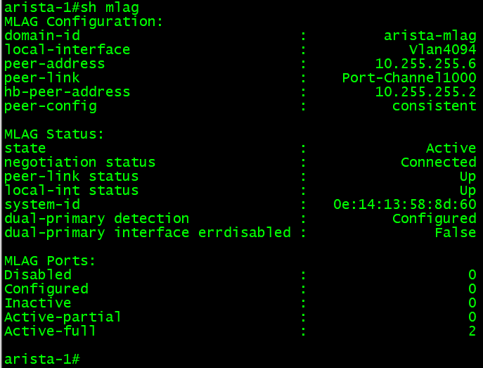
If the configuration is done, the MLAG should be working and in a consistent state. We can confirm that with some show commands.
This basic command shows an overview of the MLAG configuration and state. This is equivalent to the Cisco NX-OS command show vpc.
If all is working, both switches should appear as in the command output below, except IP addresses will differ with each peer.

The “show mlag detail” command can show more MLAG detail.
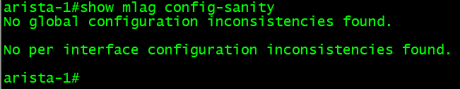
One other MLAG command that is very useful is “show mlag config-sanity.” This command will show if there are global configuration or interface inconsistencies. The command is similar to the NX-OS command “show vpc consistency-parameters global.”
Here is the interface and layer 3 information for the Arista switches:
Member Ports – Access
Connecting hosts like a switch or server is similar to Cisco’s vPC. Our first example is with a host that will connect to access ports, and in our diagram, that is the Cisco-SW switch.
In this example, the switch is connected to the Arista switches ethernet 2 ports. So, let’s configure these ports for that switch.
On both Arista switches, configure the following commands.
config
interface eth2
channel-group 2 mode active
no shut
exit
interface port-channel 2
switchport mode access
switchport access vlan 20
no shut
mlag 2
exit
Ethernet port 2 is configured in an EtherChannel and then in access mode in VLAN 20. Because the Artista switches are in MLAG and a host will be dual connected, we configure the interfaces with MLAG and, in this case, MLAG 2. The configuration is almost the same as Cisco vPC, but instead of using the “vpc 2” command, we use “mlag 2”.
Here is the command configuration for the Cisco switch Cisco-SW. Notice I set the g0 interfaces in a shutdown state, then enable them. I’ve experienced issues when applying this configuration while keeping the interfaces enabled. Sometimes one interface will come up, and the other will err-disable or not connect until the configuration is complete. To get around this, I shut both down until the configuration is done then I enable them.
config t
vlan 10
exit
vlan 11
exit
vlan 20
exit
int range g0/0,g0/1
shut
channel-group 1 mode active
exit
int port-channel 1
switchport mode access
switchport access vlan 20
no shut
exit
int range g0/0,g0/1
no shut
exit
Once this configuration is done, and on the Cisco switch, we see both interfaces up, as we can check this on the Arista MLAG pair. To check the interfaces on the Arista switches, we use the “show mlag interfaces” command.
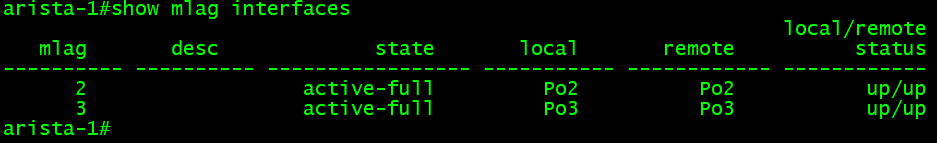
The command output should be the same on both switches, and in this command output example, the MLAG for the Cisco switch looks good; MLAG 2. MLAG 3 is the trunk switch that we will do next.
Member Ports – Trunk
Configuring member ports for a trunk is similar to the access port configuration in the previous section and on a Cisco switch. In this example, our member is a Cisco switch (Cisco-SW-Trunk) with trunk links. In this example, that switch is connected to the Arista switches ethernet 3 ports. So, let’s configure these ports for that switch.
On both Arista switches, configure the following commands.
int e3
channel-group 3 mode active
no shut
exit
int port-channel 3
switchport mode trunk
switchport trunk allowed vlan 10,11
no shut
mlag 3
exit
Now, let’s configure the Cisco switch, Cisco-SW-Trunk.
config
vlan 10
exit
vlan 11
exit
vlan 20
exit
int range g0/0,g0/1
shut
channel-group 1 mode active
exit
int port-channel 1
switchport trunk encapsulation dot1q
switchport mode trunk
switchport trunk allowed vlan 10,11
no shut
exit
int range g0/0,g0/1
no shut
exit
Once this configuration is done, and on the Cisco switch, we see both interfaces up, as we can check this on the Arista MLAG pair. To check the interfaces on the Arista switches, we use the “show mlag interfaces” command.

The command output should be the same on both switches, and in this command output example, the MLAG for the Cisco switch looks good; MLAG 3.
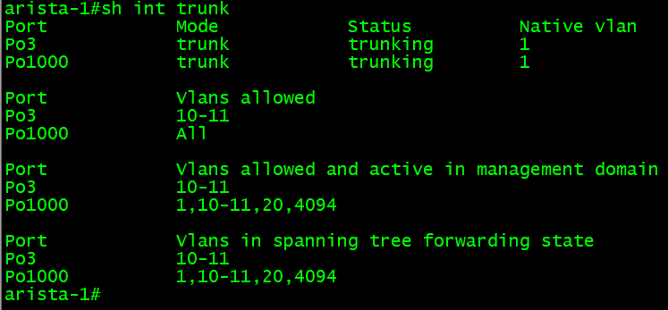
We can confirm the trunk is allowing and forwarding the configured VLANs on the Arista switches using the “show interface trunk” command.
SVI & SSH Access
For security, the management interface should be in its own VRF. If there are switched virtual interfaces (SVI) on the switch, by default, if SSH is configured, those IP addresses will allow SSH connections. One impeccable feature/command is to enable or disable SSH access per VRF.
If all the SVIs are in one VRF, for example, default and the management interface is in the mgmt VRF, SSH can be disabled for the default VRF.
Using our example, we will disable SSH to the default VRF while allowing SSH to the mgmt VRF.
arista-1(config)#management ssh
arista-1(config)#vrf mgmt
arista-1(config)#no shut
arista-1(config)#exit
arista-1(config)#shut
Using these commands, we enable SSH for the mgmt VRF, but for all others, in this example VRF default, SSH is shut down (disabled).
To view the status of SSH in general or per VRF, we can use the following commands.
arista-1#show management ssh
arista-1#show management ssh vrf mgtm
Conclusion
Having configured vPC and MLAG in a lab and production environment, I find both very similar. With both, some minor commands are not mentioned here but are not needed for a working vPC or MLAG configuration. I have used this configuration in production, but it also works well in a lab environment.
Before I used this configuration in production, I tested it in a lab using GNS3 (gns3.com); this is where I made the diagram, configuration, and command output. Fortunately, Arista makes their EOS software freely available, but you need a login account on the Arista support site. I hope you found this helpful, and as always, I appreciate any feedback.
Here are the complete configs (minus the default stuff) for each device in the topology.
Arista-1
vlan 10
exit
vlan 11
exit
vlan 20
exit
!
vlan 4094
trunk group mlagpeer
exit
!
interface eth11-eth12
channel-group 1000 mode active
exit
!
interface port-channel 1000
switchport mode trunk
switchport trunk group mlagpeer
exit
!
no spanning-tree vlan-id 4094
!
ip routing
hostname arista-1
!
vrf instance heartbeat
interface e1
no switchport
vrf heartbeat
ip address 10.255.255.1/30
no shut
exit
!
int vlan 4094
ip address 10.255.255.5/30
no autostate
exit
mlag
local-interface vlan 4094
peer-address 10.255.255.6
peer-link port-channel 1000
peer-address heartbeat 10.255.255.2
dual-primary detection delay 10 action errdisable all-interfaces
domain-id arista-mlag
exit
interface eth2
channel-group 2 mode active
no shut
exit
!
interface port-channel 2
switchport mode access
switchport access vlan 20
no shut
mlag 2
exit
int e3
channel-group 3 mode active
no shut
exit
!
int port-channel 3
switchport mode trunk
switchport trunk allowed vlan 10,11
no shut
mlag 3
exit
Arista-2
vlan 10
exit
vlan 11
exit
vlan 20
exit
!
vlan 4094
trunk group mlagpeer
exit
!
interface eth11-eth12
channel-group 1000 mode active
exit
!
interface port-channel 1000
switchport mode trunk
switchport trunk group mlagpeer
exit
!
no spanning-tree vlan-id 4094
!
ip routing
hostname arista-2
!
vrf instance heartbeat
interface e1
no switchport
vrf heartbeat
ip address 10.255.255.2/30
no shut
exit
!
int vlan 4094
ip address 10.255.255.6/30
no autostate
exit
mlag
local-interface vlan 4094
peer-address 10.255.255.5
peer-link port-channel 1000
peer-address heartbeat 10.255.255.1
dual-primary detection delay 10 action errdisable all-interfaces
domain-id arista-mlag
exit
interface eth2
channel-group 2 mode active
no shut
exit
!
interface port-channel 2
switchport mode access
switchport access vlan 20
no shut
mlag 2
exit
int e3
channel-group 3 mode active
no shut
exit
!
int port-channel 3
switchport mode trunk
switchport trunk allowed vlan 10,11
no shut
mlag 3
exit
Cisco-SW (Access Switch)
vlan 10
exit
vlan 11
exit
vlan 20
exit
int range g0/0,g0/1
shut
channel-group 1 mode active
exit
!
int port-channel 1
switchport mode access
switchport access vlan 20
no shut
!
int range g0/0,g0/1
no shut
exit
Cisco-SW-Trunk (Trunk Switch)
vlan 10
exit
vlan 11
exit
vlan 20
exit
int range g0/0,g0/1
shut
channel-group 1 mode active
exit
!
int port-channel 1
switchport trunk encapsulation dot1q
switchport mode trunk
switchport trunk allowed vlan 10,11
no shut
exit
!
int range g0/0,g0/1
no shut
exit
Reference Links:
https://www.arista.com/en/products/multi-chassis-link-aggregation-mlag
https://aristanetworks.force.com/AristaCommunity/s/article/mlag-basic-configuration
https://aristanetworks.force.com/AristaCommunity/s/article/mlag-advanced-configuration
https://www.arista.com/en/um-eos/eos-ipv4
https://community.fs.com/blog/mlag-vs-vpc-whats-the-difference.html
Copyright © Packet Passers 2025