


Last updated on February 19th, 2026 at 07:27 am
There’s no denying that the Internet is here to stay, and most businesses or organizations need Internet access for day-to-day business needs. Some small businesses and most medium to large businesses have more than one Internet connection for redundancy.
This post is not focused on large corporate Internet redundancy but small or medium businesses. Also, this can apply and primarily does for the small or medium-sized remote office. Obviously, one firewall is not redundancy, even if that firewall has two Internet Service Providers (ISP) connected.
Most of the topologies in this post include two firewalls and ISPs, as the focus is redundancy. The High Availability (HA) configuration of the firewalls in these topologies is active/passive, but many of the topologies can work with active/active. These topologies work with most firewalls, though I tend to lean on Palo Alto Network (PAN) firewalls as these are what I have primarily worked with in recent years.
Many of the topologies, especially those with dual switches and ISPs, whatever firewall model is used, rely on some type of monitor and failover mechanism. PAN firewalls in HA use the feature Link and Path Monitoring.
Topology Sections:
Two Firewalls and ISPs & WAN Switch
Two Firewalls, a WAN Switch & Simultaneous ISPs
Two Firewalls, an Internal Switch & Simultaneous ISPs
Two Firewalls, Dual Internal Switches & Simultaneous ISPs
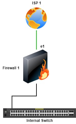
Single Firewall & ISP
This is a basic topology of one firewall and ISP, so there’s no redundancy.
In this topology, there’s still one firewall but two ISPs. If the primary ISP (ISP 1) fails, traffic fails to the other ISP (ISP 2). Each firewall manufacturer has a way for failover, usually using a monitor of some type. With PAN firewalls, this is done with Policy Based Forwarding (PFB) or, more recently, Static Route Removal Based on Path Monitoring.

Two Firewalls & ISPs
With this topology, there’s firewall and ISP redundancy. In this topology, a failure of either a firewall or an ISP provides Internet access redundancy. The PAN firewalls in a High Availability configuration provide Link and Path Monitoring to monitor a link or path on a link. In this topology, if a path monitor is configured for either a physical link or a path to an IP address fails, the firewalls can fail over to the other.

For example, on Firewall 1, if Link and Path Monitoring is configured for ISP 1 and there’s a failure, the firewalls fail over to Firewall 2, which becomes the active firewall and the path to access the Internet.

Two Firewalls and ISPs & WAN Switch
One option is to add a WAN switch to the previous topology. This topology is similar to the previous, but a WAN switch is on the ISP side, with each ISP in its own allocated VLAN. There is not much benefit to adding the WAN switch compared to the previous topology, except if another ISP or additional WAN devices are added. This would be common if multiple IP addresses are available, for example, if the company owns its IP addresses, like those provided by ARIN.
When connecting an ISP to a switch, as with this topology and those going forward in this post, consider disabling CDP and LLDP on the respective switch ports. Also, BPDU configurations must be considered on these switch ports. I’m vague on the BPDU, LLDP, and CDP configurations as there’s no set rule to enable or disable them, but they should be considered per deployment.
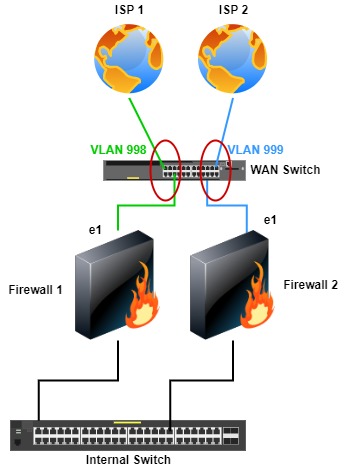
As with the previous topology, both firewalls are in HA, and the same link and path monitoring apply.
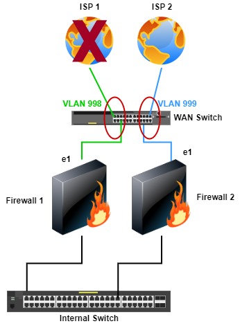
Two Firewalls, a WAN Switch & Simultaneous ISPs
We now take the previous topology to the next level. In this topology, unlike the previous, both firewalls can use both ISPs—redundancy to the next level. The WAN switch is a single point of failure, but two switches can be used with a trunk between them. I have seen inexpensive, non-redundant switches (dual power supplies or two switches) used for the WAN. There should be power and switch redundancy for how essential Internet services are and when a WAN switch is used. If cost and or management overhead is a concern to using a WAN switch(es), I will address that in the next topologies.
Because the firewalls are configured for Active/Passive, they can share ISPs and the same public IP addresses. Another benefit is that both ISPs can be used simultaneously. One con to this topology is some minor complexity, but for most Network Engineers or Administrators, not much of an issue, and the WAN switch must support multiple VLANs.
With this topology, the firewalls don’t have to fail over to the other if there is an ISP failure.

This topology can use two WAN switches which I show in a similar topology further down.
Two Firewalls, an Internal Switch & Simultaneous ISPs
If a WAN switch is unavailable or not an option, internal switches can be used. This topology is similar to the previous but uses an internal switch(es). Using internal switches removes the cost, management, and point of failure when using a WAN switch. Also, the internal switches may be of better quality and have redundancy over a WAN switch(es).
One con with this topology, which is heavily discussed or debated, is connecting ISPs to internal switches, which may be shared with other internal VLANs. If the switch(es) are updated, configured correctly, and the firewalls are configured correctly and secured, I don’t see much security risk. Again, this should be done by Network Engineers or Administrators with experience configuring and securing switches and firewalls.
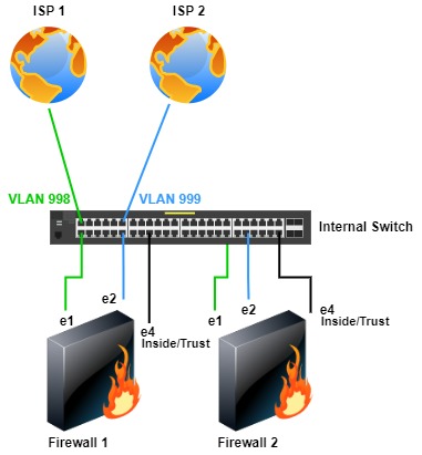
The same failover scenarios apply here as with the similar WAN switch topology.

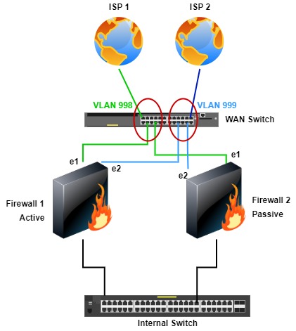
Two Firewalls, Dual Internal Switches & Simultaneous ISPs
With this topology, there’s ISP, firewall, and switch redundancy. Though this topology uses internal switches, it can be used with dual WAN switches. In this topology, firewall 1 is connected to switch 1, and firewall 2 is connected to switch 2. The switches are either a switch stack or a trunk/port channel configured between the switches. If a trunk/port channel is used, both ISP VLANs (998, 999) are allowed so that both firewalls can access both ISPs. Firewall ports e1 are connected to ISP 1 (VLAN 998), e2 to ISP 2 (VLAN 999), and e4 is the internal network (users, servers, etc..).
Again, this topology can be used with WAN switches if desired.
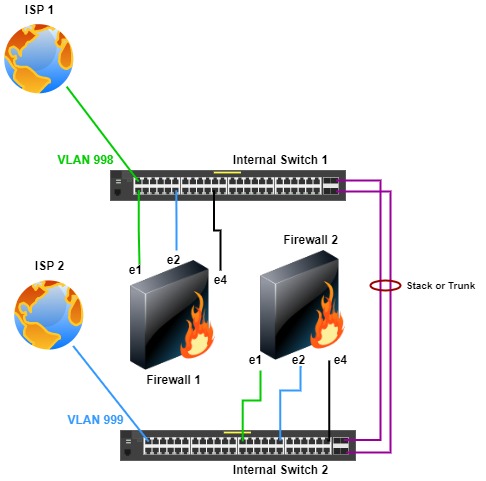
The same ISP failure scenario applies as with the previous topologies. If ISP 1 fails, the firewalls or active firewall can failover traffic to ISP 2 without fail over to the other firewall.

If there is a switch failure, as in this example with switch 1, firewall 2 in switch 2 is active and uses ISP 2. Unfortunately, anything connected (not simultaneously to switch 1 and 2) to switch 1 loses network connectivity. But, there is still some connectivity with switch 2, firewall 2, and ISP 2.
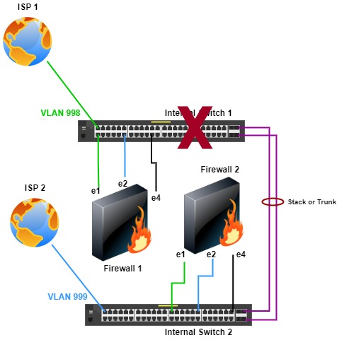
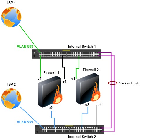
Another option with this topology is connecting firewall e1 ports for ISP 1 only to switch 1 and ports e2 to only switch 2 for ISP 2. With this topology, path and link monitoring are configured for redundancy.
Conclusion
This is not a complete list of topologies but common ones and ones I have used either recently or in the past. Some topologies can be debated as to their pros and cons; indeed, those debates or discussions are healthy for many reasons.
Careful consideration should be given to the topology based on needs, requirements, hardware (availability), compliance, and if there is a budget constraint. Today, high availability is common and available in many products or technologies and should be used wherever possible.
Reference Links (the following links may require an account with Palo Alto Networks:
https://knowledgebase.paloaltonetworks.com/KCSArticleDetail?id=kA10g000000PLL8CAO
https://knowledgebase.paloaltonetworks.com/KCSArticleDetail?id=kA10g000000ClG7CAK
Copyright © Packet Passers 2025