

Last updated on February 19th, 2026 at 07:27 am
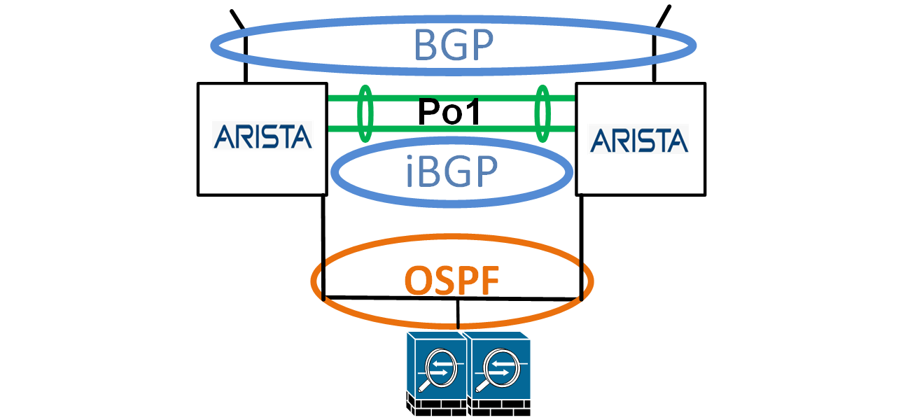
The title is not what you may think, as Arista is an excellent product suited for BGP and peering with an Internet provider. This article uses BGP, iBGP, OSPF, Arista, and Palo Alto Networks (PAN) to build a highly available dual Internet provider infrastructure.
Why the BEWARE in the title? When I was working on this topology, which is based on previous designs and experience, and now using Arista switches in place of Cisco, I encountered an issue with the default route.
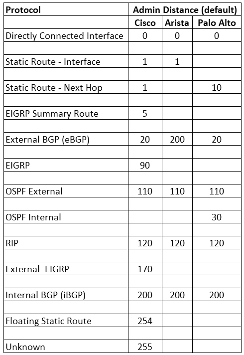
I noticed that the default route from the ISPs (using eBGP) had an administrative distance (AD) of 200. With Cisco, the default AD for External BGP (eBGP) is 20. Upon researching this behavior, I found with Arista that eBGP has an AD of 200. I then found how to change that to match Cisco by using the command “distance bgp 20 200 200” used under the BGP routing instance; link below in the Links section.
It’s essential to consider AD when working with multiple protocols and vendors, as I always kept this in mind, but this was a lesson learned not to take this for granted. Here is a chart I made comparing the AD of the three vendors in this topology.
BGP on Arista Compared to Cisco
As for the version used in this topology/article, here are some points to keep in mind when using BGP on Arista.
- BGP version 4 peering is the default
- In Cisco, the BGP configuration can use templates, but in Arista, templates are not available. Peer Groups can be used instead.
- Connect check is off by default, but it can be enabled.
- Type 7 passwords are used by default.
Topology
This topology provides redundancy at the firewall, WAN switch, and ISP levels. Most of the IP addresses used in this topology are private (based on RFC 1918) instead of public IP addresses (though some are used but are only a coincidence with any real IP addresses). The topology (image below) and testing are done with GNS3, which I have used for years, and my favorite network simulator.
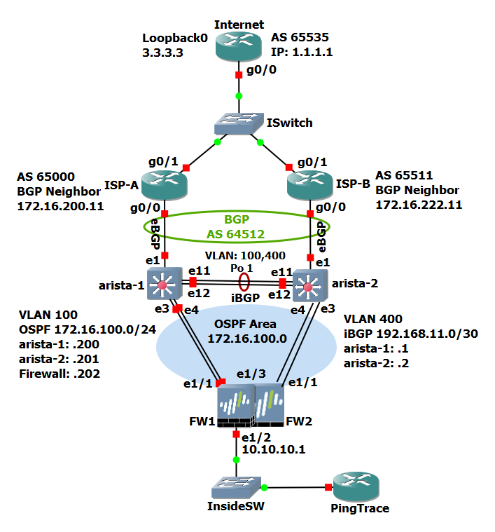
Let’s review the topology from the top down, starting from the ISPs, and work our way down.
ISPs: There are two for redundancy or if needed, load balancing. With this design, we are receiving a default route from the ISPs (0.0.0.0/0). With both, we are using eBGP with our ASN (64512) and advertising to both, our owned IP 172.16.100.0/24.
Arista Switches (layer 2): The two Arista switches have a port channel (Po1) between them, using two interfaces, e11 and e12. Both switches have VLANs 100 and 400. VLAN 100 is used for OSPF, and VLAN 400 is used for Internal BGP (iBGP). Both VLANs are allowed on the port channel. VLAN 100 has Internet edge devices with public IP addresses from our 172.16.100.0/24.
One example, and as in this topology, is the firewalls. Additional devices like the firewall(s) connect to the Arista switches and respective switch ports configured for VLAN 100.
iBGP: When BGP is used with multiple ISPs and two routers (in this case, switches), iBGP is used for routing between the two Arista switches.
OSPF: When two (or more) gateways are used, one of them is the current gateway (route) to the Internet (or other destination), devices like the firewalls need to know which is the current gateway. A First Hop Router Redundancy (FHRR) technology can be used like VRRP, HSRP, or when using Arista switches, Virtual ARP (vARP). An FHRR is commonly used, but a more dynamic solution is best.
A dynamic routing protocol like OSPF can be used for most topologies like this. Aside from being dynamic routing, OSPF is one of the fastest with convergence. OSPF advertises to the firewalls which of the two Arista switches is the current default gateway. So, for example, if ISP A is the current, active ISP and their circuit goes down, OSPF advertises to the firewalls that switch 2 (arista-2) is the current gateway.
PAN Firewalls: Firewalls are common Internet edge devices. In this topology and article (and my favorite firewall), we have two PAN firewalls in Active/Passive HA (the Passive firewall is not configured in GNS3). The firewalls provide protection and network address translation (NAT). In this topology, the host PingTrace, a Cisco router, is for testing ping and traceroutes to the Internet router (1.1.1.1 and 3.3.3.3). The firewall’s Internet-facing interfaces (e1/1) participate in OSPF.
Configuration
The following configurations are based on the topology in this article. Toward the end, I have the complete Arista switch configuration and the configuration of the ISPs, Internet, and PingTrace routers if you want to simulate this in your favorite network simulator.
Configuration – Layer 2
Let’s start by configuring the Arista switches with layer 2 configuration. Note that the version of EOS on these switches is 4.26.4M. This configuration applies to both Arista switches. I did not include the switch names (hostname).
vlan 100
name Outside-OSPF
!
vlan 400
name iBGP
!
interface Ethernet11
channel-group 1 mode active
!
interface Ethernet12
channel-group 1 mode active
!
interface Port-Channel1
switchport trunk allowed vlan 100,400
switchport mode trunk
Configuration – Layer 3 (Interface & VLAN)
Here is the interface and layer 3 information for the Arista switches:
Switch 1 (arista-1):
interface Ethernet1
description ISP-A
no switchport
ip address 172.16.200.10/31
!
interface Ethernet3
description WAN
switchport access vlan 100
!
interface Vlan100
description OUTSIDE Internet-Reachable Network
ip address 172.16.100.200/24
!
interface Vlan400
ip address 192.168.11.1/30
!
ip routing
Switch 2 (arista-2):
interface Ethernet1
description ISP-B
no switchport
ip address 172.16.222.10/31
!
interface Ethernet3
description WAN
switchport access vlan 100
!
interface Vlan100
description OUTSIDE Internet-Reachable Network
ip address 172.16.100.201/24
!
interface Vlan400
ip address 192.168.11.2/30
!
ip routing
BGP Configuration
Here is the BGP and iBGP configuration for each of the Arista switches. I won’t go into great detail about each configuration/command, but there is some helpful information. I’ll explain each line using switch 1 and provide the switch 2 configuration as the explanation applies to this switch too.
Switch 1 (arista-1):
This prefix list only allows the default route from the ISP. If you specified that the ISP only sends a default route, this is highly recommended if they accidentally send partial or all routes.
ip prefix-list Default-Route
seq 5 permit 0.0.0.0/0
This prefix list advertises only the company-owned public IP network. With dual (or more) ISPs, this prevents advertising routes from the other ISPs. I always use base prefix lists or route maps for flexibility if changes are needed, for example, allowing or blocking a subnet or padding (see route-map OUT-TO-65000 permit 10).
ip prefix-list Company-Public
seq 5 permit 172.16.100.0/24
Used in the route map “route-map iBGPRouteMap permit 10” to define the default route in iBGP. The “ip prefix-list Default-Route” could be used, but I separate them for flexibility, so a change affects one and not another (or all).
ip prefix-list iBGP-Def-Route
seq 10 permit 0.0.0.0/0
This route map can be used for parameters to apply to inbound from the ISP. This configuration sets the local preference for routes coming in on eBGP from the ISP. If we don’t set this local preference, then iBGP routes will be installed into the routing table, and a routing loop will occur. Also, we are stating that only a default route is accepted from the ISP.
route-map IN-FROM-65000 permit 10
match ip address prefix-list Default-Route
set local-preference 50
!
route-map IN-FROM-65000 deny 20
For outbound eBGP parameters with the ISP, we use this route map. In this example, we advertise the company-owned subnet 172.16.100.0/24 using prefix-list “ip prefix-list Company-Public.” This is what I was mentioning with flexibility. If we need to add any outbound parameters now or in the future, we add them here.
One example is padding, which is one of a few ways to favor one ISP inbound over another. This is done by adding the line “set as-path prepend 64512” and adding the AS number as many times as needed.
route-map OUT-TO-65000 permit 10
match ip address prefix-list Company-Public
!
route-map OUT-TO-65000 deny 20
This route map sets the local preference for the default route learned via iBGP. The “set local-preference 50” sets the iBGP learned default route to a lower preference.
route-map iBGPRouteMap permit 10
match ip address prefix-list iBGP-Def-Route
set local-preference 50
!
route-map iBGPRouteMap permit 20
The BGP instance includes the eBGP configuration with the ISP and iBGP with the other switch. To note are the timers and distance commands. BGP is slow to update when there is a change, so some configurations will massage the default BGP timers. Some will complement BGP with Bi-directional Forwarding Detection (BFD), which is beyond the scope of this article. The timers should be adjusted accordingly and carefully.
Remember the BEWARE in the title? The command “distance bgp 20 200 200” tells the Arista switch to set the AD of eBGP to 20.
Switch 1 (arista-1) BGP Routing Process Config:
router bgp 64512
timers bgp 5 20
distance bgp 20 200 200
maximum-paths 4
neighbor 172.16.200.11 remote-as 65000
neighbor 172.16.200.11 description ISP-A
neighbor 172.16.200.11 route-map IN-FROM-65000 in
neighbor 172.16.200.11 route-map OUT-TO-65000 out
neighbor 192.168.11.2 remote-as 64512
neighbor 192.168.11.2 next-hop-self
neighbor 192.168.11.2 update-source Vlan400
neighbor 192.168.11.2 description iBGP
neighbor 192.168.11.2 route-map iBGPRouteMap in
network 172.16.100.0/24
Switch 2 (arista-2) BGP Config:
ip prefix-list Default-Route
seq 5 permit 0.0.0.0/0
!
ip prefix-list Company-Public
seq 5 permit 172.16.100.0/24
!
ip prefix-list iBGP-Def-Route
seq 10 permit 0.0.0.0/0
!
route-map IN-FROM-65511 permit 10
match ip address prefix-list Default-Route
set local-preference 50
!
route-map IN-FROM-65511 deny 20
!
route-map OUT-TO-65511 permit 10
match ip address prefix-list Company-Public
!
route-map OUT-TO-65511 deny 20
!
route-map iBGPRouteMap permit 10
match ip address prefix-list iBGP-Def-Route
set local-preference 50
!
route-map iBGPRouteMap permit 20
!
router bgp 64512
timers bgp 5 20
distance bgp 20 200 200
maximum-paths 4
neighbor 172.16.222.11 remote-as 65511
neighbor 172.16.222.11 description ISP-B
neighbor 172.16.222.11 route-map IN-FROM-65511 in
neighbor 172.16.222.11 route-map OUT-TO-65511 out
neighbor 192.168.11.1 remote-as 64512
neighbor 192.168.11.1 next-hop-self
neighbor 192.168.11.1 update-source Vlan400
neighbor 192.168.11.1 description iBGP
neighbor 192.168.11.1 route-map iBGPRouteMap in
network 172.16.100.0/24
OSPF Configuration
The last configuration on the Arista switches is OSPF. I won’t go into much detail on the OSPF configuration, but much of it is straightforward. I will note with an OSPF configuration that I usually use the IP address of the participating interface for the Router ID.
Most devices support an OSPF area using a dotted-decimal format which is why the Area is 172.16.100.0. If there is a possibility of multiple adjoining OSPF Areas, then this Area should be set to 0, but in a single Area, it does not have to be Area 0. Also, the public IP address is used here for clarity.
Switch 1 (arista-1):
router ospf 1
router-id 172.16.100.200
passive-interface default
no passive-interface Vlan100
network 172.16.100.0/24 area 172.16.100.0
max-lsa 12000
log-adjacency-changes detail
default-information originate
Switch 2 (arista-2):
router ospf 2
router-id 172.16.100.201
passive-interface default
no passive-interface Vlan100
network 172.16.100.0/24 area 172.16.100.0
max-lsa 12000
log-adjacency-changes detail
default-information originate
Palo Alto Network Firewall Configuration
Here is the PAN firewall interface and OSPF configuration.
Interface e1/1 has an IP address of 172.16.100.202, which is the interface that participates in OSPF and is in the same Virtual Router (VR) as the PingTrace host.

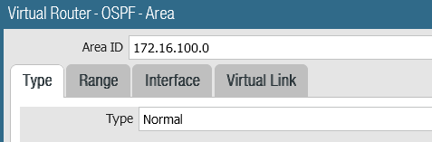
Under Network>Virtual routers> click the VR (in this example DMZ, but it may be named default), then click OSPF. Router ID, as mentioned previously, I use the device’s IP address. Add an Area ID, which in this case is the dotted decimal IP network.
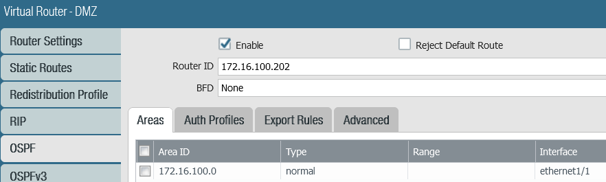
The type is Normal.
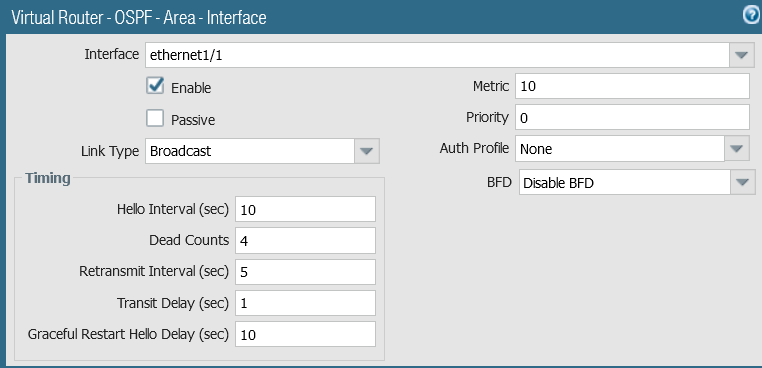
Click the Interface tab and add the interface participating in OSPF, in this case, interface e1/1.
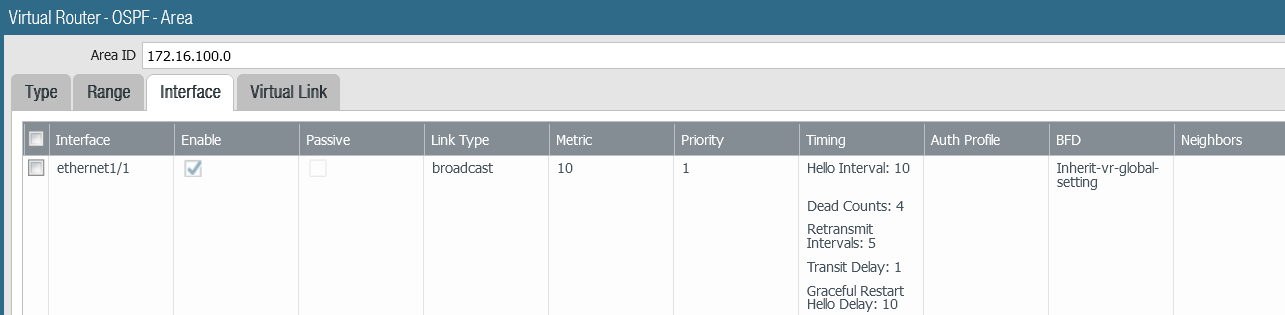
NOTE: I’ve had success with disabling BFD and setting the Priority to 0. With both Arista switches participating in OSPF, I let them become DR and BDR and not the firewall(s).
This firewall configuration section does not show the configuration of any internal interfaces (except e1/2 for the PingTrace host) and NAT, which is beyond the scope of this article.
On the PAN firewalls, don’t forget to commit the configuration.
Are we done yet?
Almost.
Once the configuration is done, there should be an eBGP peer adjacency with Arista switches 1 and 2 to their connected ISP, iBGP between the two switches, and OSPF neighborship between the firewall and two switches.
After the proper adjacencies are established and confirmed, a default route, 0.0.0.0/0, should be on each device, especially the firewall.
Pings from the PingTrace host should succeed, and traceroutes should show the path through either ISP. If ISP B is the primary route from the arista-2 switch, do “clear ip bgp *” (without the quotes). ISP A should now be the primary route to the Internet.
If you test this with a network simulator, you can shut the interface with ISP A or with GNS, suspend the ISP interface in the GUI, and confirm the default route changes to switch 2/ISP B.
Additional Options
In the original version of this article, I included options like disabling SSH, VARP, and a second VR on the firewall. Since most of those were optional and increased the length of this article, I moved them to another article, Internet BGP with Arista – Part 2.
Visit this page for information and configuration of the following:
- Disable SSH per VRF
- Permit or Deny Ping
- ISP Fallback
- VARP (HSRP or VRRP)
- Second VR on Firewall
Conclusion
Some alternative topologies or configurations accomplish the same goal as this article. As previously noted, I have successfully used this topology and configuration but with Cisco switches instead of Arista. I have known about Arista for some time, recently used their switches, and am very happy with their product.
Their CLI/command structure is similar to Cisco, so there is a low learning curve. There was a snag with the eBGP Administrative Distance, but it’s documented, and a solution is available, as noted in this article.
Arista switches have proven to be a choice for a data center or IDF and are a proven choice at the network edge. Though I have not worked extensively with their CloudVision service, it looks good and promising for those who want a graphical view, health status, and monitoring of their switch infrastructure.
Complete Configurations
Here are the complete configs (minus the default stuff) for each device in the topology (minus the PAN firewall).
Arista-1
hostname arista-1
!
vlan 100
name Outside-OSPF
!
vlan 400
name iBGP
!
interface Port-Channel1
switchport trunk allowed vlan 100,400
switchport mode trunk
!
interface Ethernet1
description ISP-A
no switchport
ip address 172.16.200.10/31
!
interface Ethernet3
description WAN
switchport access vlan 100
!
interface Ethernet11
channel-group 1 mode active
!
interface Ethernet12
channel-group 1 mode active
!
interface Vlan100
description OUTSIDE Internet-Reachable Network
ip address 172.16.100.200/24
!
interface Vlan400
ip address 192.168.11.1/30
!
ip routing
!
ip prefix-list Default-Route
seq 5 permit 0.0.0.0/0
!
ip prefix-list Company-Public
seq 5 permit 172.16.100.0/24
!
ip prefix-list iBGP-Def-Route
seq 10 permit 0.0.0.0/0
!
route-map IN-FROM-65000 permit 10
match ip address prefix-list Default-Route
set local-preference 50
!
route-map IN-FROM-65000 deny 20
!
route-map OUT-TO-65000 permit 10
match ip address prefix-list Company-Public
!
route-map OUT-TO-65000 deny 20
!
route-map iBGPRouteMap permit 10
match ip address prefix-list iBGP-Def-Route
set local-preference 50
!
route-map iBGPRouteMap permit 20
!
router bgp 64512
timers bgp 5 20
distance bgp 20 200 200
maximum-paths 4
neighbor 172.16.200.11 remote-as 65000
neighbor 172.16.200.11 description ISP-A
neighbor 172.16.200.11 route-map IN-FROM-65000 in
neighbor 172.16.200.11 route-map OUT-TO-65000 out
neighbor 192.168.11.2 remote-as 64512
neighbor 192.168.11.2 next-hop-self
neighbor 192.168.11.2 update-source Vlan400
neighbor 192.168.11.2 description iBGP
neighbor 192.168.11.2 route-map iBGPRouteMap in
network 172.16.100.0/24
!
router ospf 1
router-id 172.16.100.200
passive-interface default
no passive-interface Vlan100
network 172.16.100.0/24 area 172.16.100.0
max-lsa 12000
log-adjacency-changes detail
default-information originate
!
end
Arista-2
hostname arista-2
!
vlan 100
name Outside-OSPF
!
vlan 400
name iBGP
!
interface Port-Channel1
switchport trunk allowed vlan 100,400
switchport mode trunk
!
interface Ethernet1
description ISP-B
no switchport
ip address 172.16.222.10/31
!
interface Ethernet3
description WAN
switchport access vlan 100
!
interface Ethernet11
channel-group 1 mode active
!
interface Ethernet12
channel-group 1 mode active
!
interface Vlan100
description OUTSIDE Internet-Reachable Network
ip address 172.16.100.201/24
!
interface Vlan400
ip address 192.168.11.2/30
!
ip routing
!
ip prefix-list Default-Route
seq 5 permit 0.0.0.0/0
!
ip prefix-list Company-Public
seq 5 permit 172.16.100.0/24
!
ip prefix-list iBGP-Def-Route
seq 10 permit 0.0.0.0/0
!
route-map IN-FROM-65511 permit 10
match ip address prefix-list Default-Route
set local-preference 50
!
route-map IN-FROM-65511 deny 20
!
route-map OUT-TO-65511 permit 10
match ip address prefix-list Company-Public
!
route-map OUT-TO-65511 deny 20
!
route-map iBGPRouteMap permit 10
match ip address prefix-list iBGP-Def-Route
set local-preference 50
!
route-map iBGPRouteMap permit 20
!
router bgp 64512
timers bgp 5 20
distance bgp 20 200 200
maximum-paths 4
neighbor 172.16.222.11 remote-as 65511
neighbor 172.16.222.11 description ISP-B
neighbor 172.16.222.11 route-map IN-FROM-65511 in
neighbor 172.16.222.11 route-map OUT-TO-65511 out
neighbor 192.168.11.1 remote-as 64512
neighbor 192.168.11.1 next-hop-self
neighbor 192.168.11.1 update-source Vlan400
neighbor 192.168.11.1 description iBGP
neighbor 192.168.11.1 route-map iBGPRouteMap in
network 172.16.100.0/24
!
router ospf 2
router-id 172.16.100.201
passive-interface default
no passive-interface Vlan100
network 172.16.100.0/24 area 172.16.100.0
max-lsa 12000
log-adjacency-changes detail
default-information originate
!
end
ISP-A
hostname ISP-A
!
interface GigabitEthernet0/0
description Customer-BGP
ip address 172.16.200.11 255.255.255.254
duplex auto
speed auto
media-type rj45
!
interface GigabitEthernet0/1
description Internet
ip address 1.1.1.2 255.255.255.0
duplex auto
speed auto
media-type rj45
!
router bgp 65000
bgp log-neighbor-changes
neighbor 1.1.1.1 remote-as 65535
neighbor 172.16.200.10 remote-as 64512
!
address-family ipv4
network 1.1.1.0 mask 255.255.255.0
network 3.3.3.0 mask 255.255.255.0
neighbor 1.1.1.1 activate
neighbor 1.1.1.1 default-originate
neighbor 1.1.1.1 soft-reconfiguration inbound
neighbor 172.16.200.10 activate
neighbor 172.16.200.10 default-originate
neighbor 172.16.200.10 soft-reconfiguration inbound
exit-address-family
!
ip route 0.0.0.0 0.0.0.0 Null0
ip route 1.1.1.0 255.255.255.0 1.1.1.1
ip route 3.3.3.0 255.255.255.0 1.1.1.1
!
!
end
ISP-B
hostname ISP-B
!
interface GigabitEthernet0/0
description Customer-BGP
ip address 172.16.222.11 255.255.255.254
duplex auto
speed auto
media-type rj45
!
interface GigabitEthernet0/1
description Internet
ip address 1.1.1.3 255.255.255.0
duplex auto
speed auto
media-type rj45
!
router bgp 65511
bgp log-neighbor-changes
neighbor 1.1.1.1 remote-as 65535
neighbor 172.16.222.10 remote-as 64512
!
address-family ipv4
network 1.1.1.0 mask 255.255.255.0
network 3.3.3.0 mask 255.255.255.0
neighbor 1.1.1.1 activate
neighbor 1.1.1.1 default-originate
neighbor 1.1.1.1 soft-reconfiguration inbound
neighbor 172.16.222.10 activate
neighbor 172.16.222.10 default-originate
neighbor 172.16.222.10 soft-reconfiguration inbound
exit-address-family
!
ip route 0.0.0.0 0.0.0.0 Null0
ip route 1.1.1.0 255.255.255.0 1.1.1.1
ip route 3.3.3.0 255.255.255.0 1.1.1.1
!
!
end
Internet
hostname Internet
!
interface Loopback0
ip address 3.3.3.3 255.255.255.0
!
interface GigabitEthernet0/0
ip address 1.1.1.1 255.255.255.0
duplex auto
speed auto
media-type rj45
!
router bgp 65535
bgp log-neighbor-changes
neighbor 1.1.1.2 remote-as 65000
neighbor 1.1.1.3 remote-as 65511
!
address-family ipv4
network 1.1.1.0 mask 255.255.255.0
network 3.3.3.0 mask 255.255.255.0
neighbor 1.1.1.2 activate
neighbor 1.1.1.3 activate
maximum-paths 10
exit-address-family
!
end
PingTrace
hostname PingTrace
!
interface GigabitEthernet0/0
ip address 10.10.10.100 255.255.255.0
duplex auto
speed auto
media-type rj45
!
ip route 0.0.0.0 0.0.0.0 10.10.10.1
!
end
Reference Links:
GNS3: https://gns3.com/
Arista BGP AD Distance:
https://www.arista.com/en/um-eos/eos-border-gateway-protocol-bgp#xx1116652
PAN OSPF:
https://docs.paloaltonetworks.com/pan-os/10-1/pan-os-networking-admin/ospf
Copyright © Packet Passers 2025