Last updated on January 18th, 2023 at 08:35 am
This article compliments the first/original article for using Arista with BGP and ISP peering. In this article, I review some options that can be used in the original topology.
If you want to skip to a section, click the appropriate link:
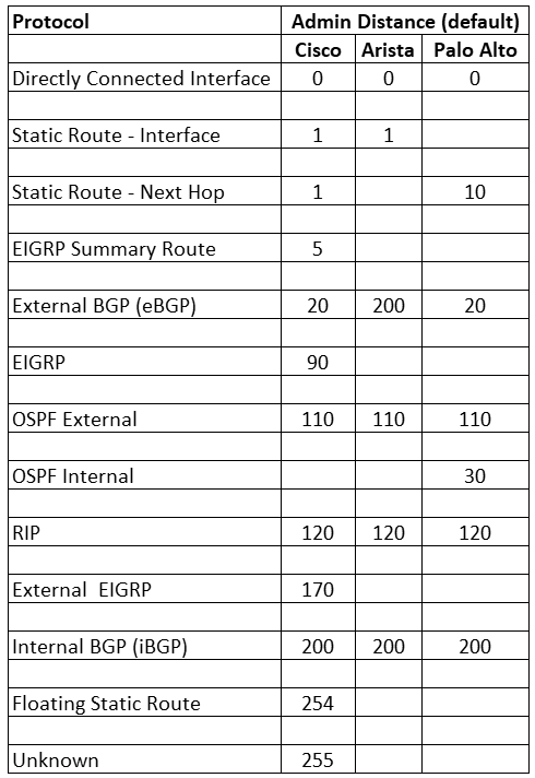
As in the first article, it’s important to know the difference between Administrative Distances with each protocol and vendor. I created this chart to be used as a cheat sheet for reference.

BGP on Arista Compared to Cisco
As for the version used in this topology/article, here are some points to keep in mind when using BGP on Arista.
- BGP version 4 peering is the default
- In Cisco, the BGP configuration can use templates, but in Arista, templates are unavailable. Peer Groups can be used instead.
- Connect check is off by default, but it can be enabled.
- Type 7 passwords are used by default.
Topology
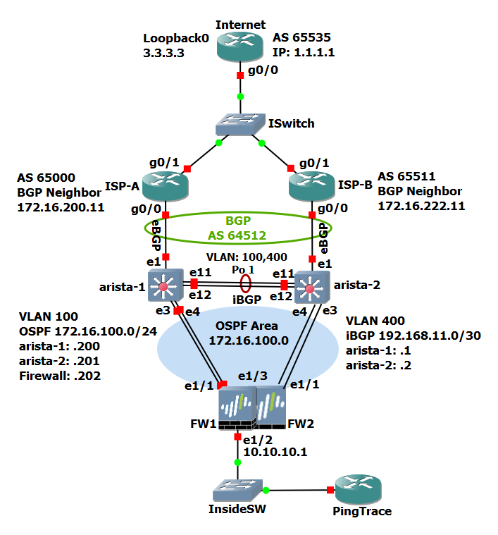
This topology provides redundancy at the firewall, WAN switch, and ISP levels. Most of the IP addresses used in this topology are private (based on RFC 1918) instead of public IP addresses (though some are used but are only coincidental with any real IP addresses). The topology (image below) and testing are done with GNS3, which I have used for years, and my favorite network simulator.

Visit the original article for more detail on the topology.
Disable SSH Per VRF – Highly Recommended
For security, the management interface should be in its own VRF. If there are switched virtual interfaces (SVI) on the switch or ports with IP addresses (with this configuration, there are), by default, if SSH is configured, those IP addresses will allow SSH connections. One impeccable feature/command is to enable or disable SSH access per VRF.
Since there are ports with IP addresses that are public/Internet-facing, SSH should be disabled for these IP addresses. In this example, by default, the interfaces with public IP addresses are placed in the default VRF.
If all the interfaces are in one VRF, for example, default, and the management interface is in the mgmt VRF, SSH can be disabled for the default VRF.
Using our example, we will disable SSH to the default VRF while allowing SSH to the mgmt VRF.
arista-1(config)#management ssh
arista-1(config)#vrf mgmt
arista-1(config)#no shut
arista-1(config)#exit
arista-1(config)#shut
Using these commands, we enable SSH for the mgmt VRF, but for all others, in this example VRF default, SSH is shut down (disabled).
To view the status of SSH in general or per VRF, we can use the following commands.
arista-1#show management ssh
arista-1#show management ssh vrf mgmt
Permit or Deny Ping – Optional but Recommended
By default, ping will be allowed to the switch ports with an IP address. In most cases, this is not wanted and especially for Internet-facing interfaces. Disabling ping is recommended and may be required for compliance or company policy.
Here we will review the commands for the access control list (ACL) to deny ping to a specific IP address but allow ping from specific sources. One reason to allow ping is for monitoring. One example is if the BGP peering ISP will monitor the interface. Another is any other monitoring, for example, you have a cloud-based network monitor service/software monitoring this interface.
Using the topology in this article, we will allow ping from two sources to 65.10.10.10 (lines 10& 20) and block all other ICMP traffic (line 30). If we don’t add a line to permit BGP (line 40), and because of the implied deny at the end of the ACL, our BGP peering will be blocked.
Caution: care must be taken when working with ACLs as during their implementation or after, wanted traffic or peering can be blocked. Like an ACL for SSH access and then blocking out your own SSH session.
ACL Configuration
Obviously, this is an example, and naming conventions and other details are based on needs and requirements. For the configuration below, use one command at a time, especially if you are not familiar with all the commands. Especially the comment command.
arista-1(config)#ip access-list restrict-ping
arista-1(config-acl-restrict-ping)#comment
arista-1(config-acl-restrict-ping)#Inbound Ping & BGP
arista-1(config-acl-restrict-ping)#EOF
arista-1(config-acl-restrict-ping)#permit icmp 192.168.99.0/24 host 65.10.10.10 echo-reply
arista-1(config-acl-restrict-ping)#permit icmp 172.16.0.0/12 host 65.10.10.10 echo-reply
arista-1(config-acl-restrict-ping)#deny icmp any host 65.10.10.10 echo-reply
arista-1(config-acl-restrict-ping)#permit tcp host 65.10.10.11 host 65.10.10.10 eq bgp
arista-1(config-acl-restrict-ping)#exit
The comment command allows the ACL to begin with a comment, which can be helpful with identification or with multiple ACLs. The EOF line ends the comment line configuration.
Since we want to block only ping, we end each permit line with echo-reply.
The last line allows BGP from our peer 65.10.10.11.
Here is the ACL on our switch with a show run command.

One helpful option is to add remarks to sections of the ACL. After reviewing the ACL in the image above, we can insert remarks before line 10 and after line 20. In this example, we will use remarks to note the start and end of the MSP monitoring.
arista-1(config)#ip access-list restrict-ping
arista-1(config-acl-restrict-ping)#5 remark Start MSP Monitor
arista-1(config-acl-restrict-ping)#25 remark End MSP Monitor
arista-1(config-acl-restrict-ping)#exit
Starting with lines 5 and 25, we insert the remark before line 10 and after 20, respectively. By doing this, we can note the start and end of the MSP monitoring ACL lines. Here is the output with a show run.

ISP Fallback – Optional
In the original configuration, the first BGP peer was the primary (route to the Internet) and the other the secondary (backup), and in some cases, this is desired. A change to the other ISP has to be done manually.
What if we want ISP A (on arista-1) to be the primary? Then if connectivity to this ISP fails, ISP B (on arista-2) will be the primary route. The configuration below will accomplish this, in addition to failing back to ISP A when peering returns with ISP A and the default route received.
Using the original topology and configuration to make make the following changes to the arista-1 and arista-2 switches, respectively.
Switch 1 (arista-1):
route-map IN-FROM-65000 permit 10
no set local-preference 50
set local-preference 200
exit
route-map iBGPRouteMap permit 10
no set local-preference 50
exitSwitch 2 (arista-2):
route-map IN-FROM-65511 permit 10
no set local-preference 50
set local-preference 100
exit
route-map iBGPRouteMap permit 10
no set local-preference 50
exitAs you can see, we changed switch 1’s inbound route map. We changed the local preference from 50 to 200. We also change switch 2’s from 50 to 100. These two changes combined make ISP A on switch 1 preferred. And, routing will fall back to switch 1 (ISP A) when peering returns and the default route is received. Similar to preemption with firewall high availability.
VARP (HSRP or VRRP) – Optional
In this configuration, the firewalls participate in OSPF for routing, but what if there’s a need to connect a device to the public/Internet side that does not support OSPF or dynamic routing? This is where we can keep the configuration in this article and add VARP, which Arista EOS uses. EOS can also use VRRP, but here we use VARP.
In this article, in VLAN 100, switch 1 has an IP address 172.16.100.200 and switch 2 .201. The virtual IP address can be 172.16.100.202. In this article, the firewalls start with .202, but these addresses can be changed, maybe the firewalls start with .203 and so forth. For the Arista switches, you can use .2 for switch 1 and .3 for switch 2, and .1 for the virtual IP, but be sure whatever you use, your consistent with the configurations.
Going forward, we will use .200 and .201 for the switches and .202 for the virtual IP.
VARP will use a MAC address to share between the switches, so we apply a MAC address for use with this command. If you blank out on being creative (like me), use an online MAC address generator.
Both switches in configuration mode:
ip virtual-router mac-address xxxx.xxxx.xxxx
Switch 1:
arista-1(config-if-Vl100)#ip address 172.16.100.200/24
arista-1(config-if-Vl100)#ip virtual-router address 172.16.100.202
Switch 2:
arista-2(config-if-Vl100)#ip address 172.16.100.201/24
arista-2(config-if-Vl100)#ip virtual-router address 172.16.100.202
With this additional configuration and if the IP addressing used is consistent, the switches will use their VLAN 100 IP addresses for OSPF and VARP. Devices in VLAN 100 that don’t support OSPF can use 172.16.100.202 as the (default) gateway.
Second VR on Firewall – Optional
If you look closely at the topology diagram, you will see not only from the firewall(s) one interface to each Arista switch but two. Interfaces e1/1 to e3 are the minimum and are used in this example for DMZ (firewall VR DMZ), which can be outbound traffic but possibly publicly accessible inbound. In the diagram, the additional interfaces are the firewall(s) interface e1/3 connected to Arista switch port e4, configured in VLAN 100.
Most network devices only allow one interface to have an IP address from the same subnet (loopback interfaces may be an exception). There is a workaround if there is a need or design to have more than one interface with an IP from the same subnet as another interface. Separate router instances/memory space on a device, usually referred to as VR or VRF (virtual route and forward), can be used.
Here is my article on VRFs, which the theory applies to many devices that support separate or multiple routing and memory spaces.
Using the image below of the network interfaces on the PAN firewall, interface e1/1 is in VR DMZ, and interface e1/3 is in VR Internet. Placing interface e1/3 in its own VR, an IP address can be used from the same IP subnet. This interface/IP can then be used for a specific reason, maybe Internet traffic from user subnets. This interface should participate in OSPF, the same as interface e1/1.

Conclusion
There are many design and configuration options, and this article is not meant to be a complete list. Security is usually a priority and should be in line with any design and configuration and should not be an afterthought. This is one of the reasons I included and highly recommend the disabling of SSH and ping on public-facing interfaces.
Also, there are multiple options, configurations, and internal company policies for BGP peering, failover, and return of services which should be discussed and reviewed internally.
Reference Links:
Arista BGP peering examples:
GNS3: https://gns3.com/
Arista BGP AD Distance:
https://www.arista.com/en/um-eos/eos-border-gateway-protocol-bgp#xx1116652
PAN OSPF:
https://docs.paloaltonetworks.com/pan-os/10-1/pan-os-networking-admin/ospf
Copyright © Packet Passers 2025


